We had now got to a stage where we could start thinking about the wiring up the Cobra. So we got the wiring loom out of the box in the shed that it had been sitting in for months. We made the decision a while ago, upon fitting a standard Hawk loom to avoid any major issues at the IVA test. It includes all switches, fuses, relays, an immobiliser kit and battery connections. The complete loom actually contains three looms, one that goes through the engine Bay, one that sits behind the dash and one that feeds the back end. These will all eventually plug together to make a complete loom.
While I was away over Christmas, Mark decided to get ahead of the game and had already spent a couple of hours marking all the connection points using masking tape to make it easier with the installation. I’m sure this will save hours of frustration in the future.
Firstly we laid the three looms out on the grass to see what we were up against. We then moved them inside and laid them over the body to get a rough idea for the route for the wires.

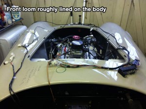
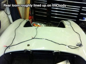
Having read about Stuart Clarkes experiences with his wiring loom we decided, as he had done, to do things a bit differently with the fuses and relays. Like Stuart, we didn’t like the idea of these being fitted on the driver’s footwell inside the engine bay and decided to follow his example and mount them inside the cabin above the steering column (Stewart actually decided to mount below the steering column). You can read about Stewarts experience here.
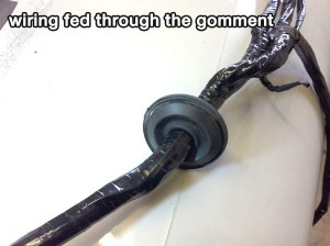
We just needed to feed the front loom through the bulkhead into the engine bay through a hole right in the corner of the bulkhead. Mark conveniently had a 40mm gommet lying spare in his tool box that would be just the job for fitting to the engine bay side of the bulkhead so the loom could easily pass through. We decided to drill a 40mm hole before carefully feeding all the loom wiring through the gomment to the position where the loom would enter the engine bay. The grommet sat in the recess quite nicely.
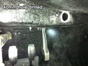

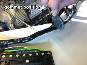
Next up was to decide how to mount the relay and fuse box. We sat and had a cuppa while we had a good think about it. We knew we had to mount some sort of bracket to the rear side of the bulk head, but we didn’t want extra bolts to be seen on the engine bay side, so thought it would be a good idea to use the same holes used to rivet the metal heat shields to also secure the brackets for this job.
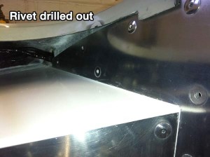
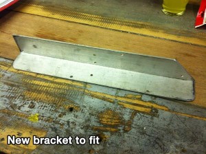
We found an old piece of right angled aluminium in the shed that we thought might just work a treat, so we measured up and cut to fit. We provisionally fitted the steering column to make sure the bracket had enough clearance (we still need to recon the steering column and fit properly…more to come on this later). We then drilled out 4 of the rivets in the bulkhead panel to then re-rivet with the bracket attached on the rear side. We thought to mount it in this position would be better for the SVA regarding potential dangers with catching bracket edges. Although this will make the relays slight more tricky to access, we didn’t see this as a big issue as modern day relays don’t fail as often as older ones.
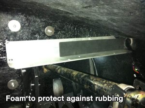
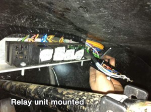
Last was to mount the relay unit to the bracket which we did with 2 small screws, We also used self adessive foam padding to protect the wire from potential chaffing against the bracket and rivets. We made an extra bracket to mount the fuse box next to the relays – More to come on this in part 2

Leave A Comment